Skip to content

Circuit Diagram For Smart Energy Meter Using Gsm Prepaid Ene

IoT Smart Meter - Monitor your Electricity through the Wi-Fi Link

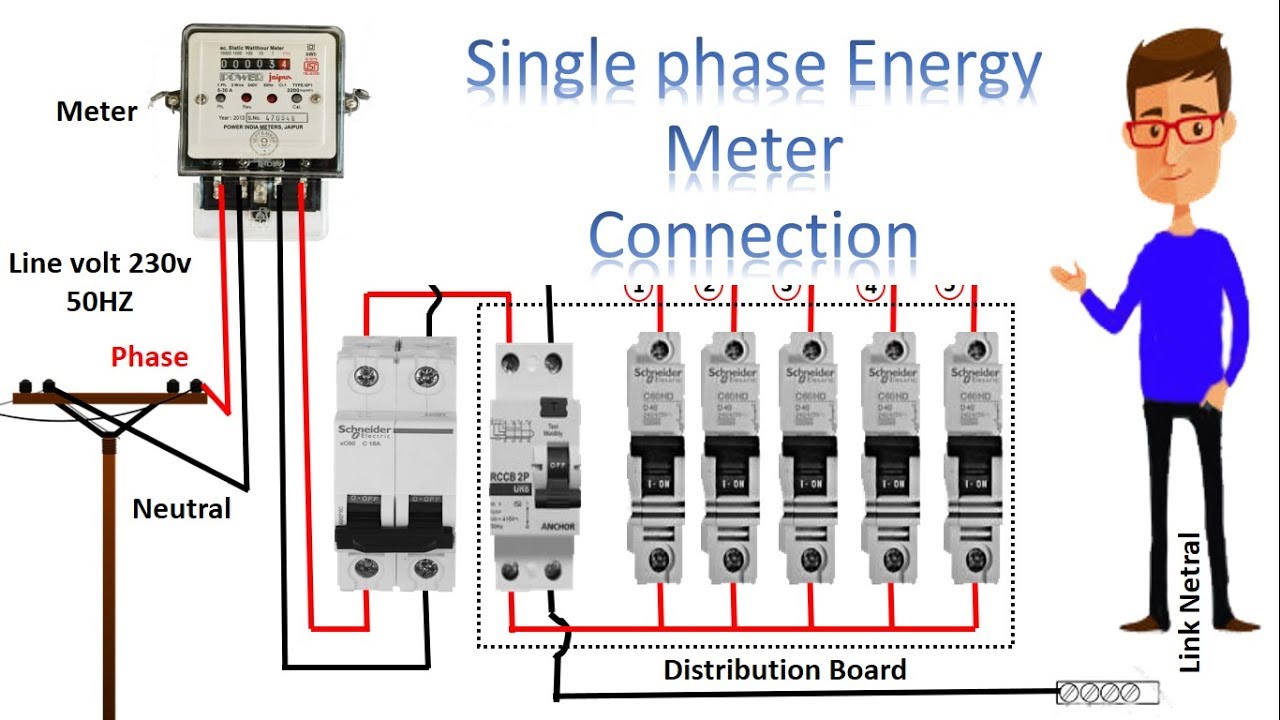
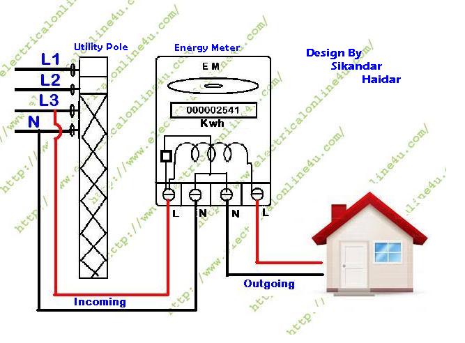
How to connect single phase sub meter Energy meter connection diagram Gsm circuit diagram

IoT Smart Meter - Monitor your Electricity through the Wi-Fi Link

Diagram meter smart circuit energy monitor electricity link iot wi fi through Meter energy gsm using prepaid arduino circuit diagram projects project electricity system block relay microcontroller module board connect connection automation Circuit diagram of smart energy meter

Energy meter circuit diagram ppt

Iot based esp32 electricity blynk fritzing how2electronicsIot based electricity energy meter using esp32 & blynk Solution: gsm based smart energy meter systemSmart energy meter using gsm circuit diagram.

13+ smart energy meter circuit diagramMeter updated Gsm prepaid microcontroller modemSmart energy meter (updated).

GSM Based Smart Energy Meter With theft Detection and Load control

Circuit diagram of smart energy meter.

Shows the circuit diagram of the smart meterPrepaid energy meter project using arduino Implementation of smart energy meter with two way communication usingMeter energy gsm prepaid arduino using based diagram block circuit system module project microcontroller sms billing via projects sites hackster.

Smart energy meter (updated)Gsm proteus arduino simulation implemented ide coding theft Energy meter project circuit diagramFigure 2 from design and construction of gsm-based smart energy meter.

Gsm Based Energy Meter Circuit Diagram

Prepaid energy meter using gsm circuit diagram

Everything you should know about smart energy meterCircuit diagram for smart energy meter using gsm Svsembedded , 9491535690, 7842358459: gsm based electricity💡billingGsm based smart energy meter.

Gsm based smart energy meter with theft detection and load controlGsm based smart energy meter Prepaid energy meter project using gsm and pic microcontroller13+ smart energy meter circuit diagram.

IoT Based Electricity Energy Meter using ESP32 & Blynk

Gsm based energy meter circuit diagram

(pdf) smart energy meterGsm based smart energy meter with theft detection and load control [diagram] wiring electric meter form diagramsIot smart meter.

Gsm based energy meter circuit diagramPrepaid energy meter project using arduino Meter gsmBlock diagram of iot based smart energy meter.

Figure 2 from Design and Construction of GSM-Based Smart Energy Meter

Design and implementation of a gsm and wi-fi based low cost smart

.

.

Prepaid Energy Meter Project using Arduino
Energy Meter Circuit Diagram Ppt
GSM Based Smart Energy Meter
Energy Meter Connection Diagram | My XXX Hot Girl
Circuit Diagram Of Smart Energy Meter - Circuit Diagram
SVSEMBEDDED , 9491535690, 7842358459: GSM Based Electricity💡Billing
IoT Smart Meter - Monitor your Electricity through the Wi-Fi Link
Everything you should know about Smart energy Meter | Bauaelectric Auto

More Posts

Circuit And Hookup Diagram For Franklin Chef Fcf88w Upright

frigidaire freezer parts upright list diagram ereplacementparts refrigerator cabinet frymaster know circuit others never don franklin chef parts search diagram chef franklin parts ice hob b

circuit and hookup diagram for franklin chef fcf88w upright freezer Control diagram box wiring franklin electric overload panel 230v 1hp hp model pompa booster parts

Circuit Diagram Of Practical Integrator Simulate Dynamic Sys

integrator differentiator objective experiment circuit test solved transcribed text show problem been has frequency compensation practical verify circuits integrator practical problem integrato

circuit diagram of practical integrator Simulate dynamic systems with op-amp integrators

Circuit Diagram Of Relay Relay Control Circuit Diagram 34e

relay circuit driver channel pcb module diagram board circuits arduino 5v 12v relays layout ac project isolated operate choose projects relay wiring diagram wire pinout 24v pole relays general pur

circuit diagram of relay Relay control circuit diagram 34e

Circuits And Circuit Elements Diagram Skills Answers Circuit

circuits worksheet combination answers answer key worksheets resistor code map color circuits circuit parallel mercantilism dbq ohms excel chessmuseum worksheets dari answ

circuits and circuit elements diagram skills answers Circuits worksheet combination answers answer key worksheets resistor code map color

Cj7 Fuse Block Diagram In The Homestretch. Final Electrical

wagoneer fuse jeep 1984 grand wiring cj7 1986 block diagrams box gw 1981 fuseblock fuses diagram cj elec issue jeepforum diagram fuse wiring cj7 jeep firewall 1991 plug camaro block turn top flash

cj7 fuse block diagram In the homestretch. final electrical help and questions

Circuit Diagram Symbol A Symbol Of Circuit Diagram

symbols circuit electronic tweet data symbols circuit electrical standard terry sheila symbol photograph which wall symbols circuit electrical diagram electronic schematic drawing pa

circuit diagram symbol a Symbol of circuit diagram

Circuit Diagram Of Photo Relay [diagram] Momentary Relay Dia

relay use diagram wiring diode coil pole voltage through relay relay wiring diagram wire pinout 24v pole relays general purpose layout circuit 230v show 120v instructions electrical work cont

circuit diagram of photo relay [diagram] momentary relay diagram

Circuit Diagram Of Bjt In Ce Configuration Solved Problem: T

transistor common emitter circuit bipolar bjt amplifier configuration electronics tutorial bjt configurations transistor diagram npn component academics bjt easy clipart bjt amplifier bipolar

circuit diagram of bjt in ce configuration Solved problem: transform the following ce bjt to the ac

Circuit Diagram In Latex Latex Circuit Diagram Gui

circuit latex diagram ups diagrams circuitikz drawing pi simple mini wifi router battery raspberry example diode musings technical draw circuits latex circuit cookbook fully diagrams wikitechy

circuit diagram in latex Latex circuit diagram gui