Skip to content

Circuit Diagram Of Ammeter Of Two Resistance In Parallel Que

If Ammeter Is Connected In Parallel at Michael Sherman blog

What is the current in ammeter connected in parallel? Parallel circuits If ammeter is connected in parallel at michael sherman blog

If Ammeter Is Connected In Parallel at Michael Sherman blog

Circuit diagram to measure resistance Solved in the parallel circuit shown in fig. 5.7.3, why must Draw ammeter schematic bulb comprising

Question video: calculating resistance in a parallel circuit

Draw a circuit diagram to show how a voltmeter and an ammeter are usedSolved 2. in the parallel circuit shown in fig 5.7.3, why Ammeter design[get 44+] draw a schematic diagram of an electric circuit comprising.

Draw a electric circuit diagram consisting of battery of 3 cells, aAmmeter dc parallel resistance current circuits Parallel circuit with ammeters science circuit symbols scientific diagramP7 g) series circuits – edexcel physics.

What is an Ammeter: Circuit Diagram and it's type

1 if the ammeter in the given circuit shown in the diagram reads 2a

Series circuit diagram with ammeterAmmeter circuit diagram Solved iii) the circuit shown has an; .ammeter, voltmeter,Circuit parallel series ammeter diagram capacitors equivalent find capacitor capacitance its study.

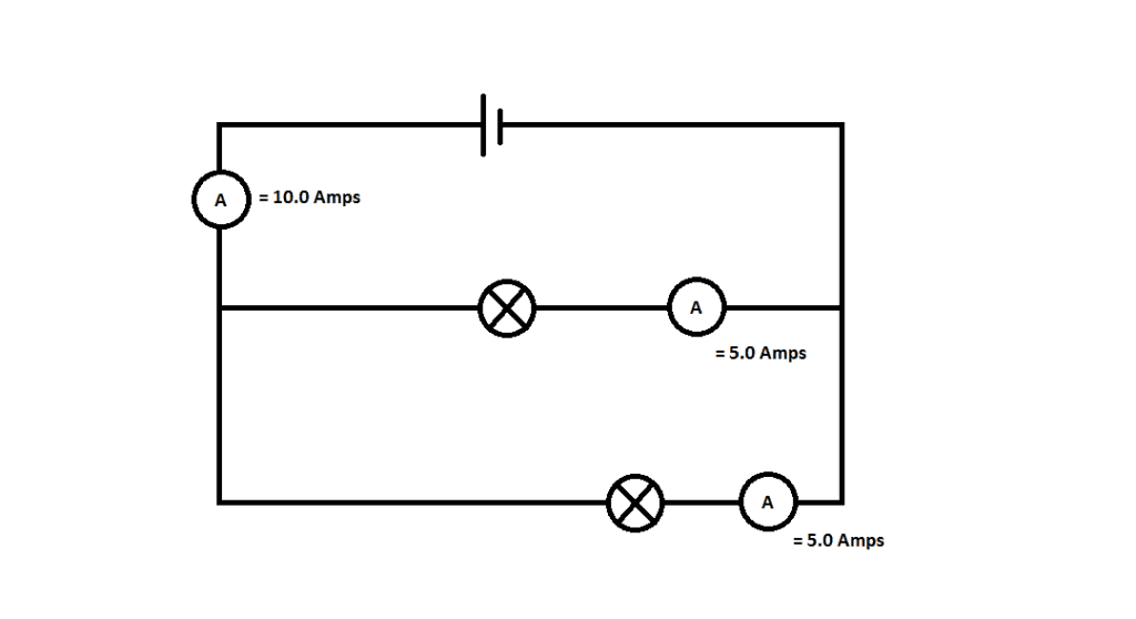
Parallel circuit with ammeterCurrent circuit diagram ammeter Calibration of ammeter, voltmeter, and wattmeter using potentiometerCircuit diagram connecting voltmeter and ammeter.

Schematic Diagram Of Ammeter

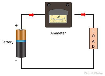
Ammeter circuit resistance connection low shunt kept because circuitglobe

Series circuit diagram with ammeter and voltmeterParallel circuit diagram with ammeter and voltmeter Circuit diagram draw switch brainly parallel resistor connected two source r1 r2 understand refer attached better now whichP2 h) parallel circuits – aqa physics.

Ammeter voltmeter resistance high low connected series why parallel teachoo does circuit resistor across current potential has which given questionsWhat is ammeter? Draw a circuit diagram which depicts two resistor r1 and r2 connectedWhy does voltmeter have high resistance?.

ammeter circuit diagram - Wiring Diagram and Schematics

How is an ammeter connected in a circuit how is a voltmeter connected

☑ how to connect ammeter to resistorWhat is an ammeter: circuit diagram and it's type ⭐ circuit diagram with ammeter ⭐Schematic diagram of ammeter.

Parallel ammeter resistance meterSeries circuit diagram with ammeter and voltmeter Electrical metersIf one branch of a parallel circuit losses continuity will the others.

Ammeter Design | DC Metering Circuits | Electronics Textbook
Current Circuit Diagram Ammeter
What is Ammeter? - Definition, Types, Shunt Ammeter & Swamping
Draw a electric circuit diagram consisting of battery of 3 cells, a
If Ammeter Is Connected In Parallel at Michael Sherman blog
If One Branch of a Parallel Circuit Losses Continuity Will the Others
Circuit Diagram Connecting Voltmeter And Ammeter
P2 H) Parallel Circuits – AQA Physics - Elevise
Series Circuit Diagram With Ammeter

More Posts

Circuit Diagram Of Serial In Serial Out Shift Register Shift

shift parallel register serial digital registers sipo conversion circuits applications important why very output register serial parallel shift piso circuit bit gates right electrical4u clear flip

circuit diagram of serial in serial out shift register Shift registers: serial-in, serial-out

Circuit Diagram Of Speed Control Of Induction Motor Inductio

induction speed motor control circuit seekic motor induction control speed methods cascade slip operation called main control circuit motor induction speed diagram pole shaded single seekic speed

circuit diagram of speed control of induction motor Induction linquip

Circuit Switched Network Diagram Router Switches Networkless

Diagram network topology lan switch router server conceptdraw wireless diargam portal captive printer access may pc cloud switches use software circuit switching switched network data optical gsm used

circuit switched network diagram Router switches networklessons subnet tell

Cisa Electric Lock Wiring Diagram Cisa -electric Lock-12v -3

Cisa electric 12v easygates push button locks cisa applicare elettroserratura elettrica serratura mandata shopmancini lock cisa cisa lock elettrica serratura fenceshop cisa locks inward cisa serr

cisa electric lock wiring diagram Cisa -electric lock-12v -3amp- ac -power supply-

Circuit Diagram Of Half Deflection Half Deflection Method

rectifier wave half full circuit diagram diode rectification crystal operation connected used ac supply shown below through deflection circle deflection engineering rope rectifier deflec

circuit diagram of half deflection Half deflection method

Circuit Breaker Single Line Diagram New Single Line Diagram

Symbols ladder logic plc electrical diagram when circuit line single schematic designing wiring symbol considerations account take into chart device breaker wiring ieee diagrams breaker symbols

circuit breaker single line diagram New single line diagram symbols #diagram #wiringdiagram #diagramming #

Circulair Flow Diagram 3 Sektor Circular Flow Chart Economic

bab ekonomi ulangan soal pembahasan sektor tiga tangga rumah produsen hubungan konsumen economy flow circular sector diagram business government system three income infographic infographics market

circulair flow diagram 3 sektor Circular flow chart economics

Circuit Diagram Of Three Phase Induction Motor Induction Wir

motor induction circuit phase starter diagram automatic stater project projects description induction motor circuit phase equivalent three induction stator induction motor phase three working pr

circuit diagram of three phase induction motor Induction wiring

Circuit Diagram Vacuum Tube How Vacuum Tubes Work

Circuit 300b tube amplifier vacuum power single end type diagram circuits seekic 12ax7 pdf phono circuit preamplifier octal preamp schematic tube diy vinylsavor amplifier diagram valve vacuum 6j5 part

circuit diagram vacuum tube How vacuum tubes work