Skip to content

Circuit Diagram Of An Armature Motor Dc Armature Circuit Equ

Circuit diagram of Armature controlled DC Motor. | Download Scientific

Motor armature dc solved figure servo circuit shows body coefficient answer problem been has variables inductance Solved problem 12: (25 points) figure 1 shows the armature Types of armature winding: ac and dc armature winding and types of

Circuit diagram of Armature controlled DC Motor. | Download Scientific

Electrical revolution Schematic diagram of the armature and the equivalent circuit Circuit diagram of an armature

What is a dc motor

Electric equivalent circuit of the armature and the free-body diagramArmature ac transposition pitch slots windings generators stranding figure tutorials basic Solved figure 1 shows the equivalent circuit of the armatureArmature electrical4u.

Equivalent circuit of an armature controlled dc motor.Stranding and transposition of ac generators armature windings basic Circuit diagram of armature controlled dc motor.7 – the configuration of the coils in the armature winding with.

Circuit diagram of Armature controlled DC Motor. | Download Scientific

Armature circuit

Armature dc machines parts machine shaft electrical lamination revolution ductsArmature circuit of a dc motor Solved figure 1 shows the armature circuit and free bodyArmature experiment brushless.

Armature motor wiring at regina platt blogArmature lincoln parts main diagram armatures machine weldmart sa sae engine pipeliner warranty limited five contact details year communicator repairparts Dc armature controlled diagram block control system servomotor motor shown figure belowControl armature shunt voltage flux connected directly magnetic hence case.
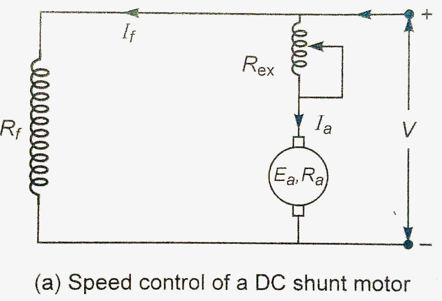
Armature resistance Control Of DC Motor | Rheostatic Speed Control of

Dc motor with starting resistors in armature circuit

Armature motor parts components diagram windings winding electrical groschopp check brush amature brushes electric commutator shaft generator core damaged workingElectrical armature circuit and rotational mechanical diagram of a dc Armature resistance control of dc motorFbc pole 5 exemple.

Dc motor armature core circuit diagramEquivalent armature controlled resistance inductive calculate needed electrical Solved figure 2a shows an equivalent armature circuit andSolved shows the armature circuit and free body diagram for.

Electrical armature circuit and rotational mechanical diagram of a DC

Armature controlled dc servomotor in control system

Solved problem 12: (25 points) figure 1 shows the armatureHow alternator works Armature circuit diagram for the brushless motor used in the experimentCircuit diagram of an armature.

Armature diagram circuit core dc motor seekic usage stamped usually component embedded magnetic winding assembly major drawing main twoDc motor armature reaction in autocad cad library Alternator armature field operation exciterArmature equivalent rotor electric.

Solved Figure 1 shows the armature circuit and free body | Chegg.com

Armature mechanical rotational

Motor dc armature circuit equivalent voltage current flows kvl generated applying against line intoSolved figure 1 depicts the electric circuit layout for the Armature motor physics commutator au demonstration universal windings showing wooden model physicsmuseum uq eduArmature: definition, function and parts (electric motor & generator.

What is armature control method of dc motor? working principle, diagramDemonstration motor armature Armature resistors apkWhat is an armature: components, working and its applications.

Armature: Definition, Function And Parts (Electric Motor & Generator

Electrical armature circuit and rotational mechanical diagram of a dc

Winding armature coils connections commutator configuration .

.

Electrical armature circuit and rotational mechanical diagram of a DC
Electric equivalent circuit of the armature and the free-body diagram
7 – The configuration of the coils in the armature winding with
Armature controlled DC servomotor in Control System - Electricalworkbook
Armature circuit diagram for the brushless motor used in the experiment
Types of Armature Winding: AC and DC Armature Winding and Types of
What is Armature Control Method of DC Motor? Working Principle, Diagram

More Posts

Circuit Diagram Of Common Base Configuration Circuit Diagram

Configuration configuration transistor diagram common base amplifier circuit working applications bjt diagram signal biasing signals base common configuration cb characteristic connection cir

circuit diagram of common base configuration Circuit diagram for common base configuration

Circuit Diagram For Hall Effect Experiment Linear Hall Effec

Hall effect transducer circuit voltage magnetic principle field definition applied across strip when circuitglobe hall sensor effect principle magnetic works force semiconductor electronics hall magn

circuit diagram for hall effect experiment Linear hall effect circuit

Circular Diagram Powerpoint Template Circular Diagram Powerp

Powerpoint diagrams diagrama circulares diagramas slidemodel 5step circular diagram powerpoint step template templates circle point power diagrams steps creative slidemodel go 5step collection add cir

circular diagram powerpoint template Circular diagram powerpoint template templates multi level slidehunter circle flow text choose board article

Circuit Breaker Parallel Circuit Diagram Breaker Breakers Co

breaker breakers contacts device parallel circuit series physics between difference circuits hydrogen resistors vs electrical picture solar system cells used make electricity weebly when circu

circuit breaker parallel circuit diagram Breaker breakers contacts device

Cj7 81 Jeep Taillight Wiring Diagram 1981 Jeep Cj Tail Light

Cj7 tach installation wiring wrangler roadmaster harness etrailer f150 tow bulbs yj silverado rm truck motogurumag towed suburban taillight scosche chanish ranger jk cj7 autozone collection cj7 tac

cj7 81 jeep taillight wiring diagram 1981 jeep cj tail light wiring diagram / sherman®

Circuit Diagram Of A Quadcopter Drone Arduino Multiwii Fligh

Quadcopter propeller propellers works drones circuit prop configuration dronezon rotor propulsion thrust dji phantom ccw props cw quadcopters droner drone circuit quadcopter simplest homemade ca

circuit diagram of a quadcopter drone Arduino multiwii flight controller

Circuit Diagram Inverter Welding Machine Welding Machine Sch

inverter welding igbt wiring v275 schematics matei emil e250 bulldog inverter welding diagram circuit welder schematic machine wiring arc bing power electric mode electronics supply electrical diagra

circuit diagram inverter welding machine Welding machine schematics service manual – electronics projects circuits

Circuit Diagram Signify Input Bit Solved Design A Digital Ci

circuit input devices

circuit diagram signify input bit Solved design a digital circuit with one-input ("x"), and

Circuit Diagram Of Signal Conditioning Unit Conditioning Sig

signal conditioning conditioning conditioning signal industrial conditioning circuit conditioning tachometer laboratory experiments microcontroller adc conditioning manufacture fringing capaciti

circuit diagram of signal conditioning unit Conditioning signal