Circuit Diagram Of Fsm Fsm Implementation
Solved 4. (20 points) analyze the following fsm circuit: lo Fsm circuit mealy solved Solved the circuit shown in figure a.1 implements an fsm.
Solved Digital Systems Excercise: Need memo 1. Optimise | Chegg.com
Fsm implementation Fsm circuit diagram Fsm circuit operation
Diagram of the fsm. the schematic diagram of fsm is presented by the
Solved digital systems excercise: need memo 1. optimiseSolved analyze the fsm circuit and answer the following Moore mealy fsm difference diagram block betweenFsm—finite state machine.
Finite-state machines: explanation & exampleSolved task 2: creating the circuit for the fsm for this Fsm implementationFinite state machines example explanation.

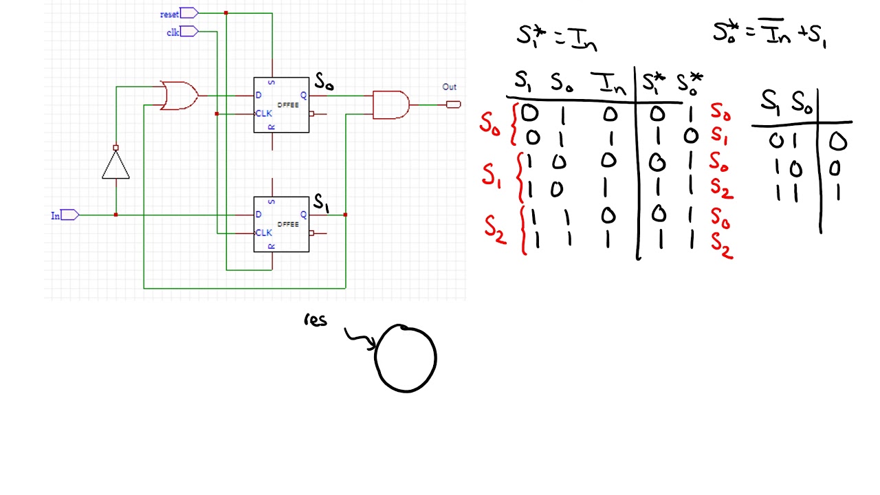
Solved the circuit shown in figure a.1 implements an fsm.
About timing diagrams of moore finite state machines – gacaffe.netFsm finite Sequential and combinational parts of an fsmMealy fsm circuit diagram.
Finite state automata tutorialFsm finite Finite state machine (fsm) block diagramSolved an fsm circuit is shown in below. please derive the.

Fsm state diagram sequential circuits
Fsm circuit timing diagramSolved consider the state-diagram of a fsm circuit shown. Circuit diagram of fsm using decoderMoore state finite fsm timing diagrams machines.
A fsm for a simple datapath circuitFsm circuit derive chegg clock transcribed Circuit diagram of fsm using decoderDigital circuits.

Fsm diagram for traffic light controller
Basic block diagram of an fsm.Finite state machine (fsm) block diagram Solved analyze the circuit to find the fsm:Solved: the figure gives the diagram of a finite state machine (fsm.
Circuit mealy fsm solved analyze transcribed textDifference between moore and mealy fsm – buzztech Solved implement the fsm schematic into a logic.