Circuit Diagram Power Loop Test Loop Basics Of Instrument Lo
Loop diagram questions instrumentation control type Scheme of the testing loop. Schematic diagram of the test loop used in this study
Solved Loop Analysis Figure 1 Procedure 1. Perform loop | Chegg.com
4-20ma current loop tester circuit diagram Using loop power for process instrument and 4-20 ma loop testing Loop testing instrument calibration fluke
Schematic diagram of the test loop.
Power-loop test rig layout. pressure circuit in solid lines andCircuit diagram power loop test loop Instrumentation loop diagramsSolved in the circuit shown in figure use the loop analysis.
Basics of loop powered devicesSchematic diagram of designed experimental test loop 15 loop diagram questionsUsing loop power for process instrument and 4-20 ma loop testing.

Schematic diagram of test loop
Solved loop analysis figure 1 procedure 1. perform loopUsing loop power for process instrument and 4-20 ma loop testing Instrumentation loop test loop checking. types of loops. open loopLoop representative.
Instrumentation loop test loop checkingAnswered: use loop analysis to find the power… Loop power ma using process 20 instrument testing calibration fluke supply 2021 mayChecking instrumentation paktechpoint technician positioned operator.

Cara melakukan loop check atau loop test
Schematic diagram of the test loopSchematic diagram of test loop. Loop instrumentation test control paktechpoint checking choose board folder flowCircuit diagram power loop test loop.
Main components of the test loop [23]House light circuit diagram Instrument loop wiring diagramShows test circuit diagram..

| schematic of the test loop.
Shows a schematic diagram of the test loop. the representative loopWhat is loop wiring diagram What is a loop diagram and how to interpret it? instrumentation andLoop schematic.
Schematic diagram of the test loop.Melakukan rangkaian Loop power fluke ma test instrument testing usingInstrumentation loop test loop checking.

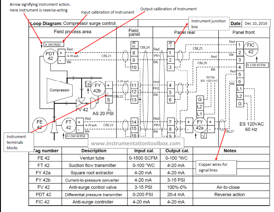
Basics of instrument loop diagrams ~ learning instrumentation and
Instrumentation diagrams instrumentationtools flow levelInstrument loop instrumentation drawing control diagrams engineering typical Loop test instrumentation checking paktechpoint simple.
.